Programming: ESP8266
Check out my other articles / projects:
- ESP8266 as a Web Server
- ESP8266 Access Point configuration GUI
- ESP8266 / OLED Calendar
- ESP8266 / OLED Date Selector
ESP8266 Access Point configuration GUI
An ESP8266 / OLED display project for connecting to an Access Point using a GUI. This project is being hosted on GitHub and (hopefully) will be contributed to by other interested developers. As such, I will not be posting any of the code on this site.
 |
Visit my GitHub repository to view the project and retrieve the latest code, notify me of errors and so forth. |
- Background
- In Operation
- Prototype using 5 Buttons
- Prototype using a KY-040 Rotary Encoder
- About the Code
- Task List
Background
There are numerous articles, projects and libraries that set the ESP8266 into Access Point mode allowing you to connect and configure an SSID and password before restarting the device in Station mode. These are great but what if you actually have a display attached to the device? Why can't the device attempt to connect to previously saved settings and if this fails, allow the user to select an Access Point and enter a pasword using a GUI?
I have used a number of screens on the Arduino but wanted this project to be compatible with the small 128x64 pixel OLED displays that have become very popular and cheap to buy. I also wanted to keep the input as simple as possible and settled on two separate input methods - 5 buttons arranged in a diamond to control movement and for selecting options and via a KY-040 rotary encoder.
The inspiration for this project came from two separate GitHub projects :- Tzapu for his amazing WifiManager project and
- Squix78 for his esp8266-oled-ssd1306 library for these little OLED displays.
Note: this project is compatible with version 2.x only. An issue in version 3.x prevents the black text from being rendered on a white packground. This has been raised as a bug in the latest version and wil be fixed soon (hopefully). This project will operate with version 3.x however the rendering of the highlights suffers.
In Operation
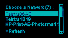
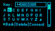
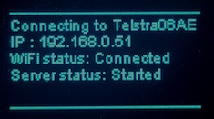
When the ESP8266 first starts it will attempt to connect to any existing SSID stored in the EEPROM using the credentials it retrieves. If this connection fails, it will then prompt the user to select an Access Point, enter a password and then connect to the WiFi. If a successful connection is made, control passes to your application otherwise the user is prompted to confirm the Access Point and / or password.
Prototype using 5 Buttons
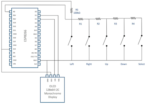
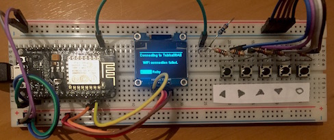
I built my prototype using some bits and pieces following the schematic shown below. The five buttons required to control the screen are connected to the ESP8266 via the ADC input freeing up the digital I/O pins for other tasks. Resistor 5 is included to form a voltage divider and split the 3.3V into (approximately) 2.3V and 1.0V as the ADC will return a value between 0 and 1023 for voltage inputs between 0V and 1.0V. Before you ask, I used the resistors I had available and they do not produce a nice spread of values. One of my tasks is to work out the correct values and alter the constants in the application accordingly.

And the prototype itself. Note that due to real estate issues, I could not arrange the four directional buttons in a diamond pattern - the stuck on piece of paper is there to remind me which button is which.

Prototype using a KY-040 Rotary Encoder
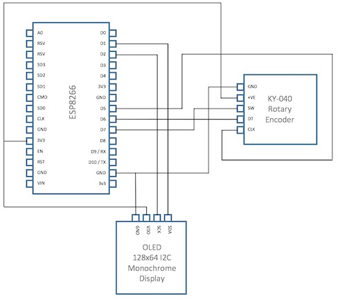
Using a rotary encoder simplifies the wiring significantly. It uses three GPIO pins for input and I have (arbitrarily) used D5, D6 and D7 (GPIO 14, 12 and 13 respectively. These are defined in the constants section of the code and can easily be changed to three unused inputs if they clash with other hardware.

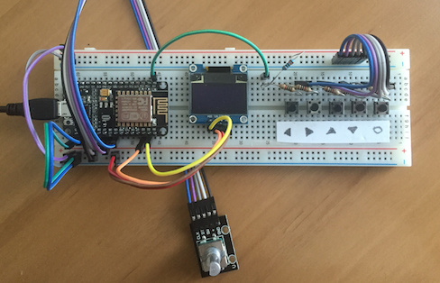
The prototype looks really messy due to it supporting both the analogue buttons and the KY-040 Rotary Encoder. I have put the encoder on a fly lead so I can use it as a sort of joystick!

About the Code
The code is packaged as a typical sketch with comments and stub code for developers to insert their own applications which take advantage of the WiFi connection created. Once the functionality has been thrashed out, the project might get redeveloped as a compiled library as per the WifiManager project.
- the code is thoroughly documented the code - well as thoroughly as any developer does!
- all constants have been pulled out into #define values where appropriate
- the code details a well defined state machine and shows how to control movement through the various connection screens and then into your own application (refer details in the code itself)
- the code includes detailed debugging which can be turned on or off in its entirety or in certain parts of the code only via a hierarchy #define structure (refer details in the code itself)
Task List
The following is a list of tasks that need to be done, may be done and could possibly be done by myself or with the help of others. I am not precious about the code and would prefer to see it completed than to sit idle ..
Publish initial code on GitHub- More testing (obvious)
- Determine some appropriate resistor sizes that provide the broadest input values (between 0 - 1023, the resistors I used provide a narrow range between 110 and 330 resulting in some errors)
- Harden the handling of the input buttons - debounce, etc
Support input via a KY-040 Rotary Encoder- Support displays of different resolutions
- Support I2C and SPI communication to OLED
- Support three buttons (left, right and select only) operation
