


Logix
Source GitHub Source
Hex Hex File
Logix is an educational game that teaches the basic logic gates used in digital electronics. Once you have completed some introductory puzzles that feature a single gate each, you can move on to harder puzzles that test your learning!


What are Logic Gates?
A logic gate is an elementary building block of a digital circuit. Most logic gates have two inputs and one output. At any given moment, every terminal is in one of the two binary conditions low (0) or high (1), represented by different voltage levels. The logic state of a terminal can, and generally does, change often, as the circuit processes data. In most logic gates, the low state is approximately zero volts (0 V), while the high state is approximately five volts positive (+5 V).
There are seven basic logic gates - AND, OR, XOR, NOT, NAND, NOR, and XNOR. This game also utilises two additional gates, the Negative-AND and the Negative-OR which are also known as NEGAND and NEGOR respectively.
AND
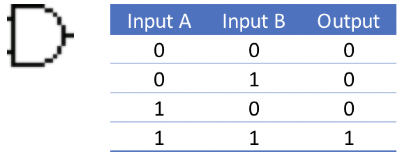
The AND gate is so named because, if 0 is called “false” and 1 is called “true,” the gate acts in the same way as the logical “and” operator. The following illustration and table show the circuit symbol and logic combinations for an AND gate. (In the symbol, the input terminals are at left and the output terminal is at right.) The output is “true” when both inputs are “true.” Otherwise, the output is “false.”
OR
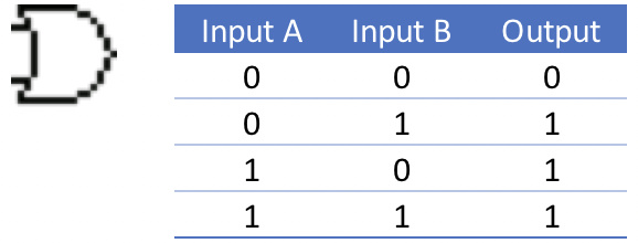
The OR gate gets its name from the fact that it behaves after the fashion of the logical inclusive “or.” The output is “true” if either or both of the inputs are “true.” If both inputs are “false,” then the output is “false.”
XOR
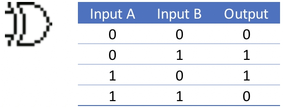
The XOR (exclusive-OR) gate acts in the same way as the logical “either / or.” The output is “true” if either, but not both, of the inputs are “true.” The output is “false” if both inputs are “false” or if both inputs are “true.” Another way of looking at this circuit is to observe that the output is 1 if the inputs are different, but 0 if the inputs are the same.
NOT
A logical inverter, sometimes called a NOT gate to differentiate it from other types of electronic inverter devices, has only one input. It reverses the logic state.

NAND
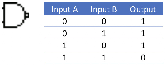
The NAND gate operates as an AND gate followed by a NOT gate. It acts in the manner of the logical operation “and” followed by negation. The output is “false” if both inputs are “true.” Otherwise, the output is “true.”
NOR
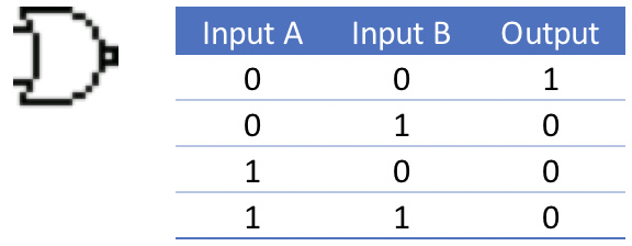
The NOR gate is a combination OR gate followed by an inverter. Its output is “true” if both inputs are “false.” Otherwise, the output is “false.”
XNOR
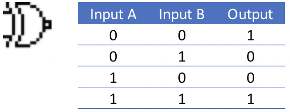
The XNOR (exclusive-NOR) gate is a combination XOR gate followed by an inverter. Its output is “true” if the inputs are the same, and"false" if the inputs are different.
Aim of the Game
Logix presents the player with a series of puzzles that test your knowledge of the basic logic gates. By wiring switches on the left of the playing field to various logic gates you can control the LEDs on the right hand side of the screen. By alternating the switch positions between on and off, the LEDs will turn on and off based on the logic you have implemented.
In each puzzle, you will be presented a chart like that shown below which details the outcomes that you must achieve to complete the puzzle.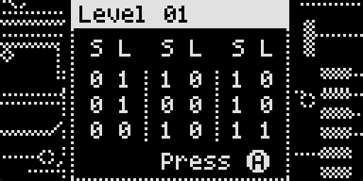 Looking at the first column, the three rows indicate that the puzzle has both three input switches and three output LEDs. The ‘S’ (switch) column indicates that the position of the switches and the ‘L’ column indicates the expected outcome of the LEDs.
When starting the game, the switches and LEDs will already be placed on the puzzle area for you. Sometimes a gate or two may also be placed in the puzzle area and this must be incorporated in the solution.
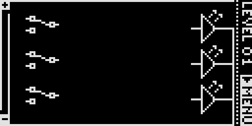 The completed puzzle is shown below. Note that the switches are all in the down / low / off position and the top two LEDs are on and the bottom one off. This corresponds to the first column of the solution outcome.
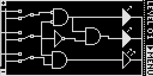 Changing the top and bottom switches to the up / high / on position turns all three LEDs off. This matches the second column of the solution outcome.
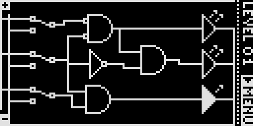
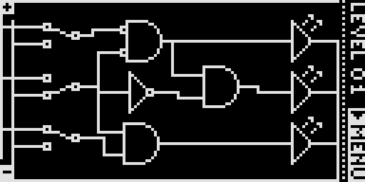 Finally, moving all switches to the up / high / on position turns the top two LEDs off and the lowest LED on. As you may have guessed, this matches the third column in the solution outcome and completes the puzzle.
A Walkthrough
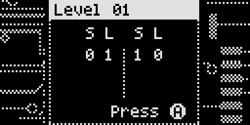
Take the example puzzle below which involves one switch and one LED. When the switch is off, the LED should be on and vice-versa. This is an example of a simple NOT circuit and makes a great starting point to learn the game.
Highlighting a Square
The selected element or gate can be changed by scrolling using the Up, Down, Left and Right buttons. You can navigate to blank spots within the puzzle and add logic gates. This is shown later on.
Wiring Elements Together
Most elements of the game have two input on the left-hand side of the element and a single out on the right. The logical NOT gate and the LED are the exceptions. The inputs and output of the selected element can be wired by pressing and holding the A button. An indicator on the upper right-hand side of the screen will indicate which of the inputs or output you are about to wire.
Releasing and repressing the A button will toggle between the three modes shown below.
 | The first mode will allow you to wire from the first input of the element to another element. |
 | The second mode will allow you to wire from the second input of an element to another element. |
 | A final release and press of the A button will reveal the output |
Back to our example. When we started the game, it showed two elements – a switch on the left-hand side and an LED on the right. Running across the top and down the left-hand side of the screen is a positive rail – running across the bottom and inset slightly from the left-hand side is a negative rail.
Typically, a switch would be wired so that when the switch is in the high position it would be connected to the positive rail. Likewise, when the switch is in the lower position, it would be connected to the negative rail. Let’s walk through doing this.
After highlighting the switch, press the A button until the top input connector is highlighted. The top input is the one that is connected to the output when the switch is in the ‘up’ position.
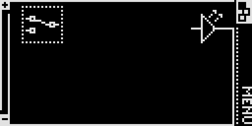
While continuing to press the A button, press the Left button to extend a ‘wire’ from the switch to the negative rail. Press the Left button a second time to continue the wire to the positive rail. As the wire is being ‘laid’ it will appear as a dotted line and will flash.
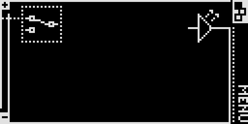
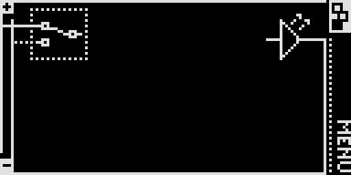
Once the wire is correctly laid and is connecting the upper input of the switch to the positive rail, release the A button. The wire will now be made permanent and will be represented as solid line.
Repeat the process to connect the lower switch input to the negative rail.
Adding new Elements
The board allows you to add up to six logic gates (in two columns of three) into each puzzle. To add an element, highlight a vacant cell and press and hold the B button. An up / down indicator will be shown in the upper right-hand side of the screen.
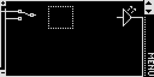
While continuing to hold the B button, press the Up and Down buttons to scroll through the available logic gate selections. In addition to the logic gates, there is a blank entry that indicates that no gate will be used. The picture below shows a AND gate selected.
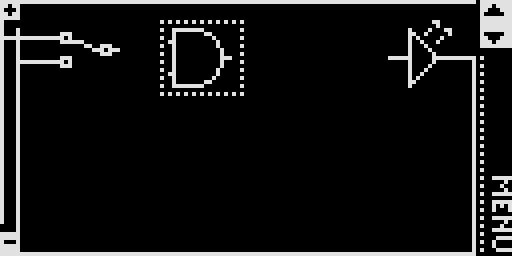
Clicking the Up button once more changes the AND into a NAND gate.
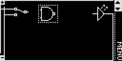
To complete the first puzzle, continue to hold the B button and scroll up and down until you have found the NOT gate. Release the B button to confirm the selection.

Tip You can change the chosen gate type by selecting an existing gate using the technique above. Changing between gates typically will not affect any wiring you have in already laid except when you swap between a gate with two inputs to the single input NOT gate or the blank.
Once the NOT gate is selected, the remainder of the wiring can be laid. Wire the output of the NOT gate to the input of the LED.
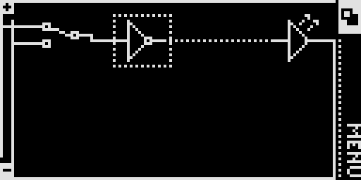
Checking your results.
After completing the wiring, we can test the results against the initial puzzle outcomes. If you recall, the original criteria was simple – when the switch is down or off, the LED is on. When the switch is up (or on) the LED is off. The original screen is shown below to remind you.
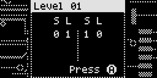
To change the switch from the lower to upper position, highlight it and press and hold the B button as if you were about to change the gate type. Pressing the Up and Down button will change the switch from the on and off / up and down positions respectively.
The image below shows the switch in the on position. When in this position, the output of the switch is high but it is inverted by the NOT gate to be low – hence the LED is off.
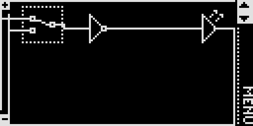
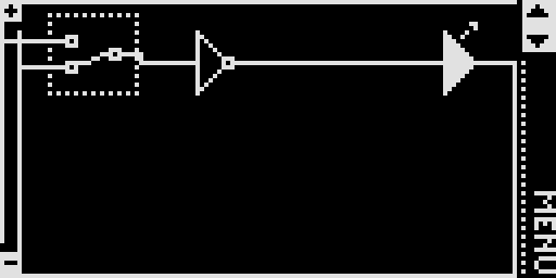
Pressing and holding the B button followed by the down button will change the switch to the down position and the output off the switch is low. This signal is inverted by the NOT gate and it in turn lights the LED as shown below.
Our tests have shown that when the switch is on, the LED is off. Conversely, when the switch is off, the LED is on. It looks like we have proven the puzzle!
Completing the Puzzle
Now that we appear to have completed the puzzle, we can check our results by navigating to the Menu option in the lower right-hand side of the screen.
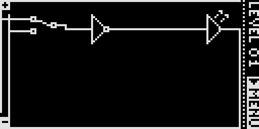
Pressing the A button will reveal the menu. Scroll down to the ‘Test’ menu and press the A button a second time.
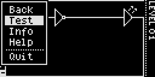
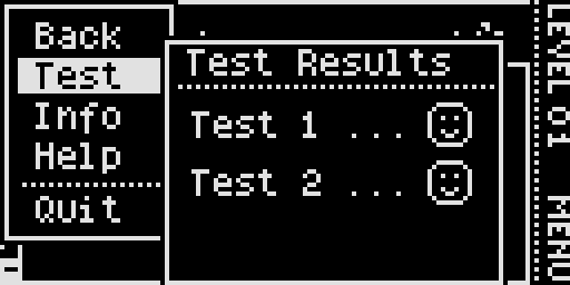
Each of the puzzle outcomes will be tested against your circuit. Feedback will be provided via the Arduboy’s LED with green meaning a correct solution and red incorrect, as well as visually with a smiley or frown face.
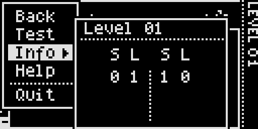
The Game menu also has some other useful options. The ‘Info’ option will repeat the pizzle outcomes that were shown at the beginning of the game.
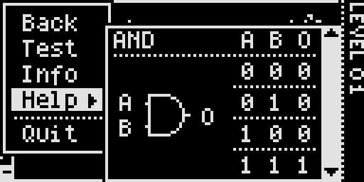
The ‘Help’ option displays the various logic gates used in the puzzles with a summary of the input states for the two inputs (A and B) and the resultant output (0). You can scroll between the gates by pressing the Up and Down buttons.
The ‘Back’ option will take you back to the game. The ‘Quit’ option will return you to the title screen.
Proceeding to the Next Puzzle
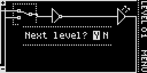
Once you have successfully completed the current puzzle, return to the game play. You will be prompted to continue to the next level if you are ready. Selecting ‘Y’ to continue of ‘N’ to remain on the current level and review your handiwork. When you do decide to move on, navigate back to the ‘Test’ menu and re-evaluate your solution.
Other Hints and Tips
| • | Levels are saved in the EEPROM. You can reset the saved levels by pressing and holding the Up and Down buttons simultaneously for 3 or 4 seconds whilst on the title screen. |
| • | You can remove a wire by laying the same wire over the top of the existing one. When you complete the second wire, the first will simply vanish! |
| • | You can wire an output to many inputs, as shown below.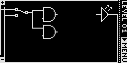 |
| • | You can wire the inputs of logic gates to either the positive or negative rails as shown below.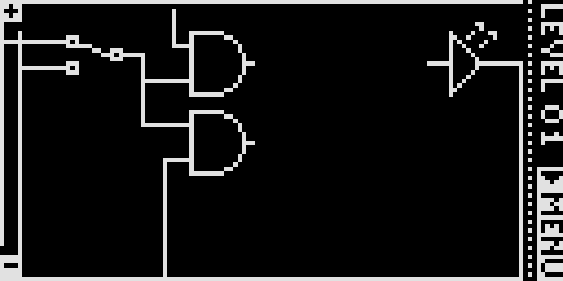 |
| • | Elements are wired from left to right – you cannot have a wire from an output loop back to the input of an element that is to the left of the current element or in the same column.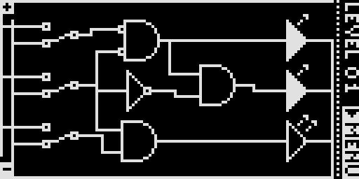 |
| • | Logic gates that are placed as part of the puzzle cannot be changed. When pressing the B button, the Up / Down indicator in the top, right-hand side of the screen is replaced with a padlock.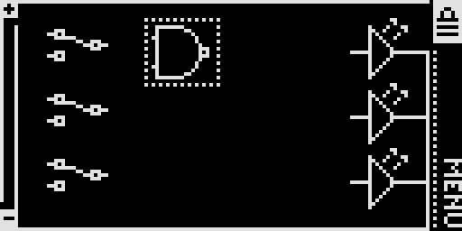 |
Play Online!
Thanks to brow1067, you can now experience the entire game - including sounds - in a web browser. Click below to start playing but be warned, there are sounds!


 Available on the
  Available on the
